Accurately measuring camlock fittings is essential for ensuring compatibility and optimal performance in fluid transfer systems. Proper measurements guarantee a secure, leak-free connection, preventing costly downtime and potential safety hazards. Camlock fittings, with their various types and sizes, require precise measurements to match connecting components.
This guide provides a step-by-step approach to measuring camlock fittings, covering crucial dimensions such as adapter and coupler diameters, cam arm distance and length, and gasket specifications. Understanding these measurements allows for informed selection, ensuring seamless integration and efficient operation of your fluid transfer systems.
What Are Camlock Fittings
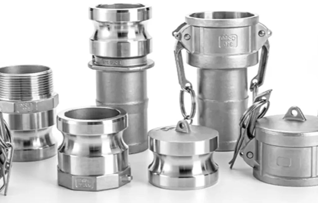
Camlock fittings, also known as cam and groove couplings, are quick-connect couplings used for rapidly connecting hoses and pipes in various industrial applications. They consist of a male adapter and a female coupler, which are connected by inserting the adapter into the coupler and locking the cam arms. This design allows for tool-free connections and disconnections, making them highly efficient.
- Quick-Connect Couplings: Designed for rapid connections.
- Male Adapter and Female Coupler: Two main components for connection.
- Cam Arms Locking Mechanism: Securely locks the adapter into the coupler.
- Tool-Free Operation: Enables fast connections and disconnections.
- Versatile Industrial Use: Employed in various fluid and material transfer applications.
How to Measure Camlock Fittings?
Accurately measuring camlock fittings is essential for ensuring compatibility and proper function in fluid transfer systems, especially when dealing with wholesale quantities. These measurements determine the fitting’s size and type, guaranteeing a secure and leak-free connection.
Here’s a step-by-step guide to measuring camlock fittings for wholesale purposes:
Tools Needed:
- Caliper (digital or vernier)
- Measuring tape
- Ruler or straight edge
- Notebook and pen (for recording measurements)
- Sample fittings from various batches (for consistency checks)
- Manufacturer’s specification sheets (for reference)
Step 1. Identify the Camlock Fitting Type
Begin by visually inspecting the types of camlock fittings. Camlock fittings come in various types, including A, B, C, D, E, F, DC, and DP. Each type has distinct features and connection mechanisms. Note the specific type of fitting you are working with, as this will influence subsequent measurements.
Accurate identification of the camlock fitting type is crucial for proper measurement and selection. Each camlock type has unique dimensions and connection methods, requiring specific measurement points. Incorrect identification can lead to inaccurate measurements and incompatible fittings. Understanding the fitting type ensures that you target the correct areas for measurement.
This initial step sets the foundation for the entire measurement process. Taking time to correctly identify the camlock fitting type will prevent errors later. Ensure that you are familiar with the characteristics of each camlock fitting type before proceeding. Proper identification leads to a more efficient and accurate measurement process.
Step 2. Determine the Camlock Fitting Nominal Size
Locate any markings or labels on the camlock fitting that indicate its nominal size. This size, typically expressed in inches, corresponds to the inner diameter of the hose or pipe the fitting is designed to connect. Record this nominal size, as it provides a reference for overall dimensions and compatibility.
The nominal size is a key reference point for understanding the fitting’s intended application. It indicates the approximate size of the hydraulic hose or pipe that the fitting is designed to accommodate. While it is not a direct measurement, it helps in verifying compatibility with other components. Documenting the nominal size ensures that you have a consistent point of reference.
This step is essential for ensuring that the measured fitting is compatible with the intended system. The nominal size helps in understanding the general scale of the fitting. Correctly determining and recording the nominal size ensures that the measurements are placed into proper context.
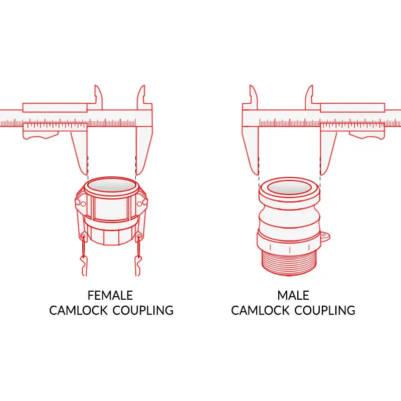
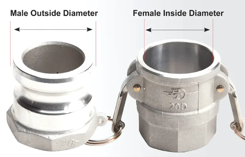
Step 3. Measure the Male Adapter’s Outside Diameter (OD)
Using a caliper, carefully measure the outside diameter (OD) of the male adapter. Position the caliper jaws across the widest points of the adapter, ensuring they are perpendicular to the adapter’s axis. Record this measurement accurately.
Measuring the male camlock fitting adapter’s OD is crucial for determining its compatibility with the female coupler. Accurate measurement ensures a tight and secure connection. The caliper jaws should be positioned carefully to avoid any skewing that could lead to inaccurate readings. Record the measurement immediately to avoid errors.
This step requires precision to ensure a proper fit. The OD measurement directly impacts the fitting’s ability to create a leak-free seal. Use a digital caliper for increased accuracy. Ensure the caliper is calibrated before taking measurements.
Step 4. Measure the Female Coupler’s Inside Diameter (ID)
Using a caliper, measure the inside diameter (ID) of the female coupler. Place the caliper jaws inside the coupler, ensuring they are positioned at the widest points. Record this measurement accurately.
The ID of the female coupler must match the OD of the male adapter for a secure connection. Accurate measurement is essential to prevent leaks and ensure proper functionality. Position the caliper jaws carefully to obtain a precise reading. Record the measurement immediately to avoid errors.
This step is vital for ensuring compatibility between the male adapter and female coupler. The ID measurement determines the fitting’s ability to create a tight seal. Use a digital caliper for increased accuracy. Ensure the caliper is properly positioned to obtain the correct measurement.
Step 5. Measure the Adapter Flange Diameter
If the male adapter has a flange, measure its diameter using a caliper or measuring tape. Position the measuring tool across the widest points of the flange and record the measurement.
The flange diameter is essential for determining the overall dimensions of the fitting. This measurement is crucial for ensuring compatibility with other components in the system. Use a caliper for precise measurements, especially for smaller flanges. Record the measurement immediately.
This step ensures that the flange dimensions are accurately recorded. The flange diameter is important for ensuring proper alignment and connection. Take multiple measurements to verify accuracy.
Step 6. Measure the Coupler Flange Diameter
If the female coupler has a flange, measure its diameter using a caliper or measuring tape. Place the measuring tool across the widest points of the flange and record the measurement.
The flange diameter of the female coupler is essential for ensuring compatibility with other components. Accurate measurement is crucial for proper alignment and connection. Use a caliper for precise measurements, especially for smaller flanges. Record the measurement immediately.
This step ensures that the flange dimensions are accurately recorded. The flange diameter is important for proper alignment and connection. Take multiple measurements to verify accuracy.
Step 7. Measure the Distance Between Cam Arms (Open Position)
With the cam arms on the female coupler in the open position, measure the distance between the inside edges of the cam arms using a caliper or ruler. Record this measurement.
The distance between the cam arms is crucial for ensuring proper engagement with the male adapter. Accurate measurement ensures that the adapter can be securely locked into place. Use a caliper for precise measurements. Record the measurement immediately.
This step is vital for ensuring the camlock mechanism functions correctly. Proper cam arm spacing is essential for a secure connection. Verify the cam arms are fully open before measuring.
Step 8. Measure the Cam Arm Length
Measure the length of one cam arm from its pivot point to the end using a ruler or straight edge. Repeat for the other cam arm and record both measurements.
The cam arm length is essential for ensuring proper locking and release of the camlock mechanism. Accurate measurement ensures that the cam arms provide adequate leverage. Use a ruler or straight edge for accurate measurements. Record the measurements immediately.
This step ensures that the cam arms are of the correct length. Cam arm length impacts the ease of connection and disconnection. Verify the pivot point and end point of each cam arm before measuring.
Step 9. Measure the Gasket Outside Diameter (If Applicable)
If the fitting includes a gasket, measure its outside diameter using a caliper or measuring tape. Place the measuring tool across the widest points of the gasket and record the measurement.
The gasket’s OD is crucial for ensuring a proper seal. Accurate measurement prevents leaks and ensures the gasket fits correctly. Use a caliper for precise measurements. Record the measurement immediately.
This step ensures that the gasket dimensions are accurately recorded. The gasket OD impacts the fitting’s sealing capabilities. Verify the gasket is properly seated before measuring.
Step 10. Measure the Gasket Thickness (If Applicable)
If the fitting includes a gasket, measure its thickness using a caliper. Position the caliper jaws on opposite sides of the gasket and record the measurement.
The gasket thickness is essential for ensuring a proper seal. Accurate measurement prevents leaks and ensures the gasket is compressed correctly. Use a caliper for precise measurements. Record the measurement immediately.
This step ensures that the gasket thickness is accurately recorded. The gasket thickness impacts the fitting’s sealing capabilities. Verify the gasket is properly seated before measuring.
Step 11. Record All Measurements
Carefully record all measurements in your notebook, noting the fitting type and size alongside each measurement. This detailed record will ensure accuracy and prevent errors when selecting or replacing camlock fittings.
Accurate recording of all measurements is vital for preventing errors and ensuring proper fitting selection. Documenting measurements immediately after taking them prevents memory lapses. Ensure the notebook is organized and clearly labeled.
This step ensures that all measurements are properly documented. An organized record is essential for avoiding confusion and ensuring accuracy. Clearly label each measurement with the corresponding fitting part.
Camlock Fitting Size Chart
Selecting the correct camlock fitting size is crucial for ensuring a secure and efficient fluid transfer system. The size of the fitting directly impacts its flow capacity and compatibility with hoses or pipes. Camlock fittings offer a range of sizes to accommodate diverse industrial needs, from small-scale applications to large-volume fluid transfers. Understanding these size variations is essential for efficient and safe operations.
Camlock fittings typically range from ½ inch to 6 inches in diameter, depending on the material. Aluminum, brass, and stainless steel fittings are available across this full spectrum, while polypropylene fittings are generally offered in sizes up to 4 inches. The size chosen should correspond to the internal diameter of the hose or pipe being connected to ensure a proper fit. For smaller sizes, such as ½ inch, fittings often come standard with two handles for enhanced security and manageability.
Size Range:
- ½ inch to 6 inches for Aluminum, Brass, and Stainless Steel.
- ½ inch to 4 inches for Polypropylene.
Handle Configuration:
½ inch fittings typically include two handles.
Material Variation:
Materials include Aluminum, Brass, Stainless Steel, and Polypropylene.
Application Compatibility:
Size choice corresponds to hose or pipe internal diameter.
Camlock Fitting Size Chart
| Size (Inches) | Typical Material | Typical Applications |
| ½ | Aluminum, Brass, Stainless Steel, Polypropylene | Small volume fluid transfer, garden hoses |
| ¾ | Aluminum, Brass, Stainless Steel, Polypropylene | Medium volume fluid transfer, light industrial |
| 1 | Aluminum, Brass, Stainless Steel, Polypropylene | General purpose fluid transfer, construction |
| 1 ½ | Aluminum, Brass, Stainless Steel, Polypropylene | Industrial fluid transfer, chemical handling |
| 2 | Aluminum, Brass, Stainless Steel, Polypropylene | Large volume fluid transfer, tank trucks |
| 3 | Aluminum, Brass, Stainless Steel | Heavy-duty industrial, large volume transfers |
| 4 | Aluminum, Brass, Stainless Steel, Polypropylene | High volume fluid transfer, industrial plants |
| 6 | Aluminum, Brass, Stainless Steel | Very high volume transfers, specialized applications |
Conclusion
Accurately measuring camlock fittings is essential for ensuring compatibility and proper function in fluid transfer systems. Precise measurements guarantee a secure, leak-free connection, preventing costly downtime and potential safety hazards. Understanding the dimensions of each fitting component, from diameters to cam arm distances, is crucial.
Proper measurement techniques ensure that the selected camlock fittings meet the specific requirements of your application. This meticulous approach avoids mismatches, ensuring a reliable and efficient fluid transfer process. Regular verification of fitting dimensions is also recommended to maintain system integrity and prevent leaks.
For high-quality wholesale camlock fittings tailored to your precise measurements, contact DF Hydraulics today. We offer a comprehensive range of durable and reliable fittings, ensuring efficient and secure fluid transfer solutions. Get in touch to discuss your specific needs and benefit from our expert services.