Accurately measuring hydraulic fittings is crucial for ensuring proper installation and system performance. Incorrect measurements can lead to leaks, improper connections, and even system failures.
This guide will provide you with essential tips and techniques for accurately measuring various types of hydraulic fittings, including thread size, overall length, and other critical dimensions. Whether you’re a seasoned mechanic or a DIY enthusiast, understanding how to measure hydraulic fittings correctly will save you time, money, and frustration.
How to Measure Hydraulic Fittings
Accurately measuring hydraulic fittings is crucial for ensuring proper installation, compatibility, and the overall performance and safety of your hydraulic system. Incorrectly sized or mismatched fittings can lead to leaks, reduced system efficiency, and even catastrophic failures.
This guide delves into the intricacies of measuring hydraulic fittings, providing a comprehensive process of hydraulic fitting measurement.
Tools Required
Essential Tools for Measuring Hydraulic Fittings:
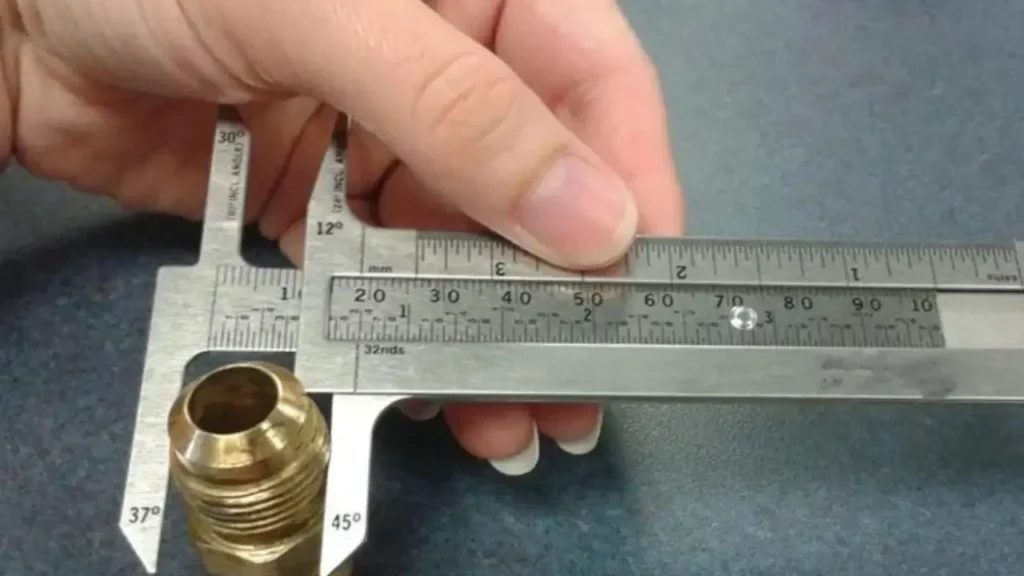
- Calipers: Measure thread diameters, overall length, and O-ring groove dimensions.
- Thread Pitch Gauge: Determine the distance between adjacent threads.
- Reference Charts: Compare measurements with industry standards and identify fitting types.
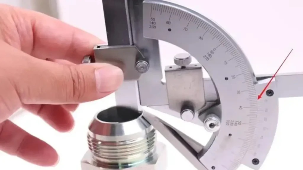
- Protractor: Measure the flare angle of flared fittings.
Remember:
- Keep tools clean.
- Take multiple measurements.
- Wear safety glasses.
Step 1: Determine the Type of Hydraulic Fittings
This initial step is crucial as it dictates the subsequent measurement techniques and the interpretation of the results.
- Visual Inspection:
- Thread Profile: Carefully observe the thread profile. Are they straight (like NPT), tapered, or have a specific angle (like JIC)?
- Sealing Mechanisms: Identify any sealing features such as O-ring grooves, flared surfaces, or flat faces.
- Fitting Configuration: Note the fitting’s orientation: straight, elbow, tee, or other configurations.
- Manufacturer Markings: Check for any markings or stamps that might indicate the manufacturer or model number.
- Reference Materials:
- Utilize comprehensive fitting identification guides or charts available online or in industry publications.
- Cross-reference visual cues with the guide to confirm the fitting type.
- Consult manufacturer catalogs if available for specific model identification.
- Consider Application:
- The application of the fitting can provide clues to its type. For example, high-pressure applications often utilize ORFS fittings, while automotive brake systems may employ banjo fittings.
Step 2: Measuring Thread Diameter
- Select the Appropriate Tool:
- Use a high-quality caliper, preferably a digital caliper for enhanced accuracy and ease of reading.
- For internal threads, a depth micrometer might be necessary for more precise measurements.
- Clean the Threads:
- Ensure the threads are free of debris, dirt, or any foreign matter.
- Clean the threads with a clean cloth or compressed air if necessary.
- Proper Caliper Placement:
- Male Threads:
- Position the caliper jaws perpendicular to the thread axis.
- Measure the outer diameter (OD) of the threads.
- Take multiple measurements at different points along the thread length to average out any slight variations.
- Female Threads:
- Position the caliper jaws within the internal threads.
- Measure the inner diameter (ID) of the threads.
- Ensure the caliper jaws are parallel to the thread axis.
- Male Threads:
Step 3: Determining Thread Pitch
- Use a Thread Pitch Gauge:
- This specialized tool is designed to accurately measure the distance between adjacent threads.
- Select the gauge with the appropriate thread pitch range.
- Place the gauge on the threads and find the matching pitch.
- Manual Calculation (for TPI):
- If a thread pitch gauge is unavailable, you can manually calculate the threads per inch (TPI).
- Measure the distance along the thread axis that covers a known number of threads.
- Divide the measured distance by the number of threads to determine the TPI.
- Ensure Accurate Measurement:
- Clean the threads before measurement.
- Position the gauge or ruler accurately and perpendicular to the thread axis.
- Repeat measurements to ensure accuracy and consistency.
Step 4: Measuring Seat Angles (if applicable)
This step is crucial for flared fittings such as JIC and 45-degree fittings.
- Select the Appropriate Tool:
- Use an angle finder or a protractor with a magnetic base for easier placement.
- Clean the Fitting:
- Ensure the flared surface is clean and free of debris.
- Position the Angle Finder:
- Place the angle finder against the flared surface, ensuring full and even contact.
- For accurate readings, the angle finder must be securely positioned without any movement.
- Read the Angle:
- Read the angle from the angle finder’s scale.
- Repeat measurements at different points on the flared surface to ensure consistency.
Step 5: Measuring Fitting Length
- Select the Appropriate Tool:
- Use a caliper or a ruler for accurate length measurements.
- For longer fittings, a measuring tape might be necessary.
- Define Measurement Points:
- Clearly define the starting and ending points of the measurement.
- This might include the overall length, the length of the threaded portion, or the distance between specific features on the fitting.
- Ensure Accurate Placement:
- Place the measuring tool perpendicular to the fitting’s axis.
- Ensure the fitting is positioned on a flat, stable surface.
- Take multiple measurements to ensure accuracy and consistency.
Step 6: Cross-referencing Measurement Results
- Compare Measurements with Standards:
- Refer to relevant SAE standards (e.g., SAE J514 for JIC fittings) or manufacturer specifications for the expected dimensions.
- Compare your measured values with the specified dimensions.
- If discrepancies exist, investigate the cause and re-measure if necessary.
- Consult Fitting Charts and Tables:
- Utilize fitting charts and tables available online or in industry publications.
- Cross-reference your measurements with the dimensions listed in these resources to identify the fitting type and size.
- Consult with Our Experts:
- If you encounter any difficulties or uncertainties, consult with a qualified hydraulic technician or engineer.
- They can provide expert guidance and assist with complex measurement situations.
By following these steps and utilizing appropriate tools and techniques, you can accurately measure hydraulic fittings, ensuring proper selection, installation, and the overall reliability of your hydraulic systems.
How to Measure JIC Hydraulic Fittings
Measuring JIC Hydraulic Fittings
JIC (Joint Industry Council) fittings are a common type of hydraulic fitting known for their 37-degree flare. Accurately measuring these fittings is crucial for ensuring proper installation and system compatibility.
Here’s a breakdown of the key measurements:
1. Thread Size:
- Measure the thread diameter: Use a caliper to measure the outer diameter (OD) of the male threads or the inner diameter (ID) of the female threads.
- Determine the thread pitch: Measure the distance between adjacent threads using a thread pitch gauge. Alternatively, count the number of threads per inch (TPI).
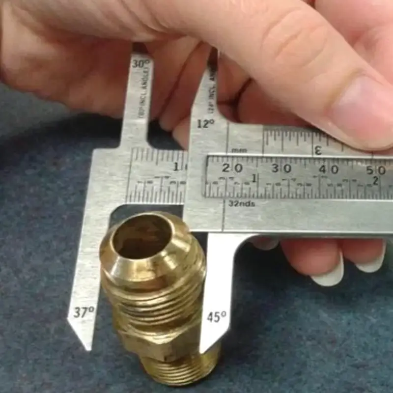
2. Flare Angle:
- Use an angle finder: Position the angle finder against the flared surface of the fitting and read the angle. JIC fittings have a standard 37-degree flare angle.
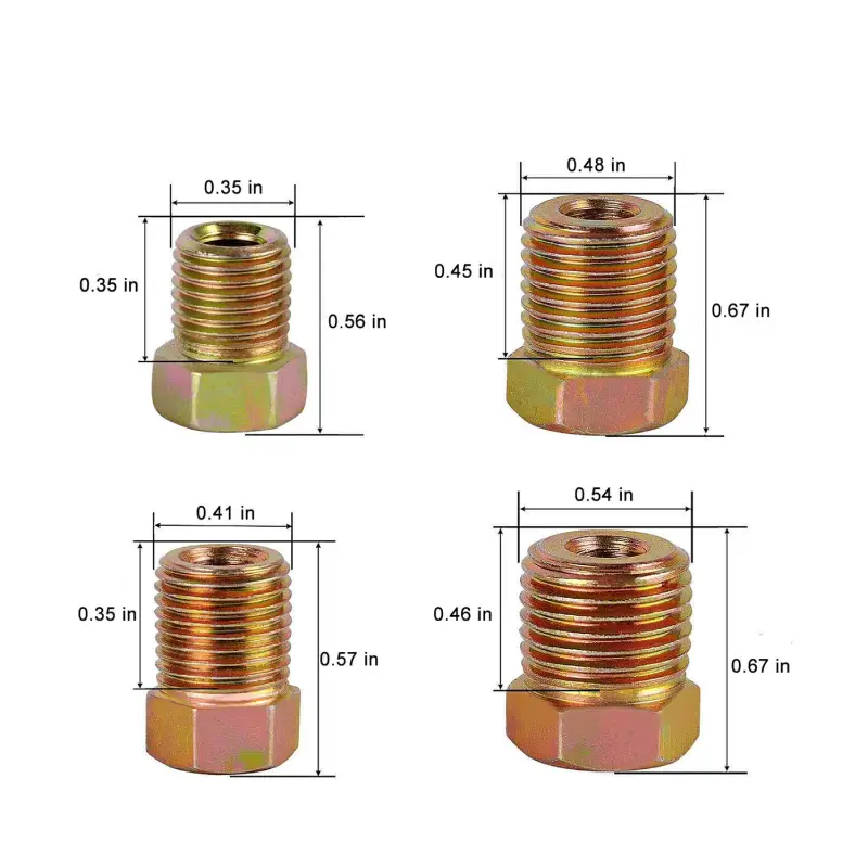
3. Overall Length:
- Measure the total length of the fitting: Use a caliper or ruler to measure the overall length, including the threaded portion and any other features.
4. Other Dimensions:
- For specific applications: You may need to measure other dimensions such as the hex size (for wrenching) or the distance between the center of the fitting and the centerline of the bolt hole (for certain mounting configurations).
Important Considerations:
- Cleanliness: Ensure the fitting is clean and free of debris before measuring.
- Accuracy: Take multiple measurements and average the results to ensure accuracy.
- Reference Materials: Consult JIC standards and manufacturer specifications for precise dimensional data.
By accurately measuring these key dimensions, you can ensure proper selection and installation of JIC fittings, minimizing the risk of leaks and maximizing system performance.
How to Measure BSP Hydraulic Fittings
Measuring BSP Hydraulic Fittings
BSP (British Standard Pipe) fittings are commonly used in hydraulic systems, particularly in European applications. Accurately measuring these fittings is crucial for ensuring compatibility and proper installation.
Here’s how to measure BSP fittings:
1. Determine Thread Size:
- Measure the Outer Diameter (OD): Use a caliper to measure the outer diameter of the male threads or the inner diameter of the female threads.
- Calculate the Nominal Size: BSP thread sizes are typically determined by subtracting 25% from the measured OD.4 For example, if the OD is 1 inch, the nominal size would be 0.75 inches (3/4 inch).
2. Determine Threads Per Inch (TPI):
- Count the Threads: Count the number of thread crests within a specified length (e.g., 1/4 inch).
- Calculate TPI: Multiply the number of threads counted by 4.
3. Identify the BSP Standard:
- BSPP (British Standard Pipe Parallel): These fittings have parallel threads.
- BSPT (British Standard Pipe Tapered): These fittings have tapered threads.
4. Cross-Reference Measurements:
- Consult BSP Thread Size Charts: Use a comprehensive chart that lists BSP thread sizes, corresponding ODs, and TPI values.
- Match your measurements to the chart to determine the exact BSP size and type (BSPP or BSPT).
5. Measure Other Dimensions:
- Overall Length: Measure the total length of the fitting, including the threaded and unthreaded portions.
- Other Relevant Dimensions: Measure any other relevant dimensions, such as the diameter of the fitting body or the depth of any grooves or recesses.
Important Considerations:
- Clean the Fitting: Ensure the fitting is clean and free of debris before measuring.
- Use Accurate Tools: Employ high-quality calipers and measuring tools for precise measurements.10
- Take Multiple Measurements: Repeat measurements to ensure accuracy and consistency.
- Consult Reference Materials: Refer to industry standards and manufacturer specifications for the most accurate and up-to-date information.
By following these steps, you can accurately measure BSP hydraulic fittings, ensuring proper selection, installation, and the overall reliability of your hydraulic system.
Conclusion
Accurately measuring hydraulic fittings is essential for ensuring proper installation, compatibility, and system performance. By carefully measuring key dimensions such as thread size, overall length, and O-ring groove dimensions (if applicable), you can select the correct fittings for your application.
For high-quality, precision-engineered hydraulic fittings, choose Kingdaflex. We offer a wide range of fittings designed to meet the most stringent industry standards. Contact us today to learn more about our products and how we can help you optimize your hydraulic systems.