Accurately measuring AN fittings is crucial for ensuring proper connections and preventing leaks in high-performance fluid systems. These fittings, designed to military specifications, require precise measurements to guarantee compatibility and optimal performance.
This blog post will guide you through the essential steps and tools needed to measure AN fittings correctly. We’ll cover the key dimensions, including thread size, flare angle, and overall length, providing clear instructions to help you select the right fittings for your application.
What Are AN Fittings

AN fittings, short for Army-Navy fittings, are high-performance connections designed for fluid transfer in demanding environments. They adhere to stringent military specifications, ensuring consistent quality, reliability, and interchangeability. This standardization is crucial for applications where precision and durability are paramount.
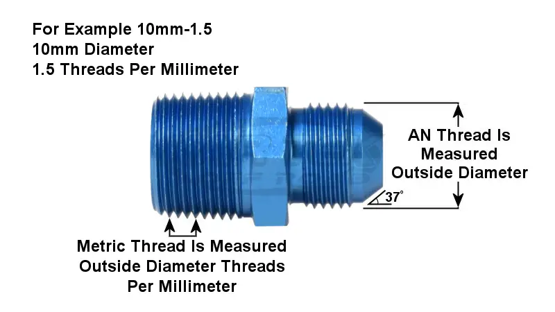
These fittings are renowned for their 37-degree flared connection, which creates a robust, leak-free seal capable of withstanding high pressures and extreme temperatures. This design makes them ideal for critical systems where failure is not an option.
AN fittings are commonly used in aerospace, motorsports, and heavy-duty industrial applications. They are typically made from high-grade materials like aluminum or stainless steel, offering excellent corrosion resistance and mechanical strength. Their widespread adoption in these industries underscores their reputation for superior performance and reliability.
How to Measure an Fittings
Measuring AN fittings accurately is crucial for ensuring proper system functionality and preventing leaks.
Here’s a detailed guide about AN fitting mesaurement:
Tools Required for Measuring AN Fittings
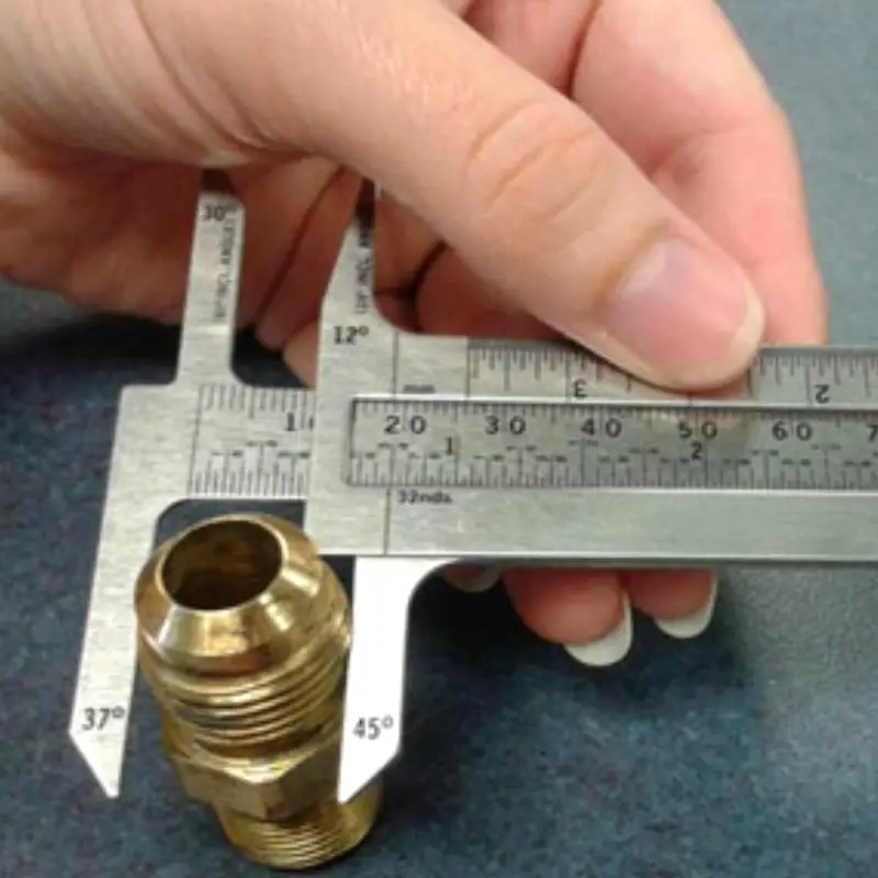
To accurately measure AN fittings, you’ll need a few essential tools. These include a high-quality digital caliper, a thread pitch gauge, and a 37-degree flare angle gauge. Digital calipers provide precise measurements of diameters, while thread pitch gauges help determine the thread size. A flare angle gauge ensures the flare angle is correct, crucial for AN fitting compatibility. Having these tools will help achieve precise measurement and prevent errors.
These tools should be well maintained, and calibrated. Worn out calipers, or thread pitch gauges will give inaccurate readings. Also, make sure that the tools are clean. Debris on the measuring surfaces of the tools can lead to inaccurate measurements.
Step-by-Step Guide to Measuring AN Fittings
Measuring the Diameter
- Step 1: Clean the fitting thoroughly. Ensure that there is no dirt or debris that could interfere with the measurement.
- Step 2: Use a digital caliper to measure the outside diameter (OD) of the fitting’s threads. Place the caliper jaws on the outermost points of the threads and record the measurement.
- Step 3: Measure the inside diameter (ID) of the fitting’s bore, if applicable. Carefully place the caliper’s inner jaws inside the bore and record the measurement.
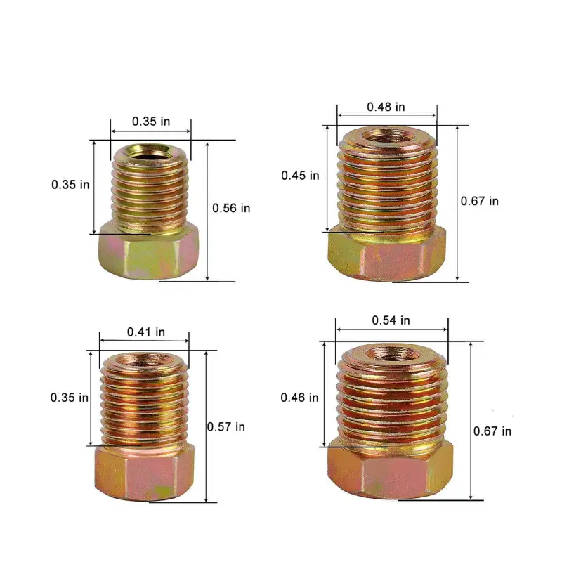
- Step 4: Consult an AN fitting size chart to match the measured diameters to the corresponding AN size. AN sizes are typically indicated by a dash number, which represents the nominal OD in sixteenths of an inch. For example, a -6 AN fitting has a nominal OD of 6/16 inch (3/8 inch).
Measuring the Thread Size
- Step 1: Use a thread pitch gauge to determine the thread pitch. Align the gauge’s teeth with the fitting’s threads until a perfect match is found.
- Step 2: Identify the thread type, such as UNF (Unified National Fine) or NPT (National Pipe Thread). AN fittings typically use UNF threads, but it’s essential to verify.
- Step 3: Use a thread size chart to confirm the thread size based on the pitch and type. This will help identify the exact thread specification.
- Step 4: If there is any doubt about the thread type or size, compare the fitting to known samples or consult a thread identification guide.
Measuring the Flare Angle
- Step 1: Use a 37-degree flare angle gauge to check the angle of the fitting’s flare. Position the gauge against the flared surface to ensure a perfect match.
- Step 2: Verify that the flare surface is smooth and free from damage. Any imperfections can affect the sealing performance.
- Step 3: If the flare angle deviates from 37 degrees, the fitting is not a standard AN fitting and may not be compatible with other AN components.
- Step 4: Visually inspect the flare for any signs of damage, such as cracks, dents, or uneven surfaces. These defects can compromise the fitting’s ability to create a leak-free seal.
Common Mistakes to Avoid
Using Worn or Damaged Tools
Using worn or damaged tools can lead to inaccurate measurements, resulting in improper fitting selection and potential system failures. Tools like calipers and thread pitch gauges should be regularly inspected and replaced when necessary. Worn tools can have loose jaws or damaged threads, leading to inconsistent readings.
Always ensure your tools are in good condition. Regularly calibrate digital calipers and replace thread pitch gauges with worn teeth. Proper tool maintenance is essential for accurate measurements.
Measuring Dirty or Contaminated Fittings
Measuring dirty or contaminated fittings can introduce errors due to debris interfering with the measurement points. Dirt, grease, and other contaminants can alter the dimensions of the fitting, leading to incorrect readings. Always clean fittings thoroughly before measuring them.
Use a clean cloth or solvent to remove any dirt or debris from the fitting’s surfaces. Ensure the measurement points are free from obstructions to obtain accurate readings.
Assuming the Flare Angle
Assuming the flare angle instead of verifying it can lead to compatibility issues. AN fittings have a 37-degree flare angle, but other fittings may have different angles. Always use a flare angle gauge to confirm the angle.
Never assume the flare angle. Always verify it with a gauge. Ensure the gauge is clean and properly aligned with the flare surface for accurate verification.
Inconsistent Measurement Techniques
Inconsistent measurement techniques, such as applying varying pressure on the calipers or misaligning the thread pitch gauge, can result in inaccurate readings. Develop a consistent measurement technique and practice it regularly to ensure accuracy.
Apply consistent pressure on the calipers and align the thread pitch gauge properly. Practice measuring fittings regularly to develop a consistent and reliable technique.
Ignoring Calibration and Tool Accuracy
Ignoring calibration and tool accuracy can lead to significant measurement errors. Digital calipers and other measuring tools require regular calibration to ensure accuracy. Follow the manufacturer‘s calibration guidelines and schedule regular calibrations.
Always verify the calibration status of your tools. Use calibrated tools to ensure accurate measurements and prevent errors.
Overlooking the Importance of Double-Checking
Overlooking the importance of double-checking measurements can lead to costly mistakes. Always double-check your measurements to ensure accuracy. Verify the readings and compare them to known standards.
Double-check all measurements and compare them to AN fitting size charts. Ensure the measurements are consistent and accurate.
Selecting the Most Suitable AN Fitting
Determine the Application Requirements
Before selecting an AN fitting, determine the specific requirements of the application. Consider factors such as pressure, temperature, fluid type, and flow rate. Understanding these requirements will help choose the appropriate fitting size, material, and type.
Identify the operating conditions of the system, including pressure and temperature ranges. Determine the fluid type and its compatibility with the fitting material.
Select the Appropriate Fitting Size
Choose the fitting size based on the measured dimensions and the required flow rate. AN sizes are indicated by dash numbers, which represent the nominal OD in sixteenths of an inch. Refer to an AN fitting size chart to match the measured dimensions to the appropriate size.
Match the measured diameters and thread sizes to the corresponding AN size on the chart. Select a fitting size that can handle the required flow rate and pressure.
Choose the Right Material
Select the fitting material based on the fluid type and environmental conditions. AN fittings are typically made from aluminum or stainless steel. Aluminum is suitable for general-purpose applications, while stainless steel offers excellent corrosion resistance and durability.
Consider the fluid compatibility and environmental factors, such as exposure to corrosive substances or extreme temperatures. Choose a material that can withstand the operating conditions.
Evaluate Environmental Factors
Evaluate environmental factors, such as temperature, humidity, and exposure to corrosive substances. These factors can affect the fitting’s performance and longevity. Choose fittings that are suitable for the operating environment.
Consider the operating environment and its potential impact on the fitting’s performance. Select fittings that can withstand the environmental conditions and maintain their integrity.
AN Fitting Size Chart
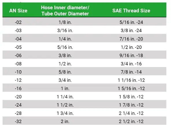
AN fitting sizes are designated by a dash number, which represents the nominal outside diameter (OD) of the fitting in sixteenths of an inch. For example, a -4 AN fitting has a nominal OD of 4/16 inch, or 1/4 inch. This dash number system simplifies the identification and selection of fittings, ensuring compatibility within hydraulic systems.
These size charts typically include information on the nominal OD, thread size, and recommended tubing size for each AN fitting. It’s important to note that these are nominal sizes, and actual dimensions may vary slightly depending on the manufacturer and materials used. Always consult the manufacturer‘s specifications for precise measurements.
Accurate use of an AN fitting size chart is essential for preventing leaks and ensuring proper system function. Incorrectly sized fittings can lead to significant performance issues and potential system failures. Regularly referencing these charts during installation or maintenance is crucial for maintaining system integrity.
When using an AN fitting size chart, pay close attention to the thread type and pitch, as well as the flare angle. While AN fittings primarily use a 37-degree flare, variations may exist in specialized applications. Understanding these nuances will help ensure a secure and reliable connection.
Conclusion
Accurate AN fitting measurement is vital for system integrity, preventing leaks and ensuring proper function. Identifying size and thread type is key, using calipers and reference charts for precision. Misinterpreting measurements can lead to costly errors and system failures.
For high-quality wholesale AN fittings, choose DF Hydraulics. We provide a wide selection of sizes and materials to meet your specific needs, ensuring reliable performance in demanding applications.
Visit the DF Hydraulics website today to explore our inventory and request a wholesale quote. Our expert team is ready to assist you in selecting the perfect AN fittings for your projects.