When working with JIC fittings, precision is key to ensuring the correct connection and preventing leaks. In this guide, I will walk you through how to measure JIC fittings accurately, covering essential aspects like thread dimensions, cone angles, and sealing surfaces.
Whether you are new to the hydraulic industry or an experienced technician, understanding how to measure JIC fittings is crucial for selecting the right components. If you have any questions about the content, feel free to contact us for further clarification.
What are JIC Fittings?
Before diving into how to measure JIC fittings, it’s important to understand what JIC fittings are and where they are used.
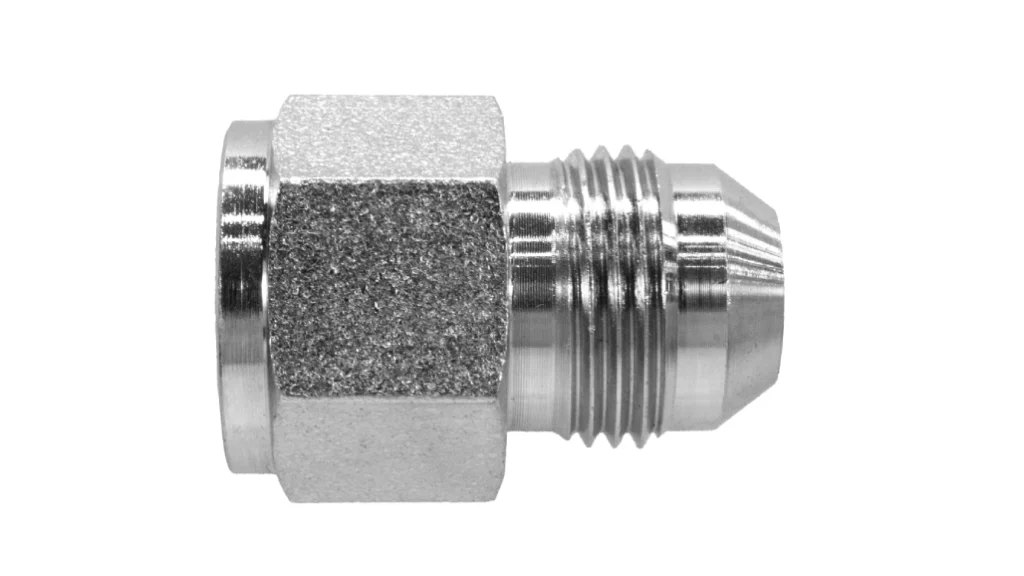
Structure:
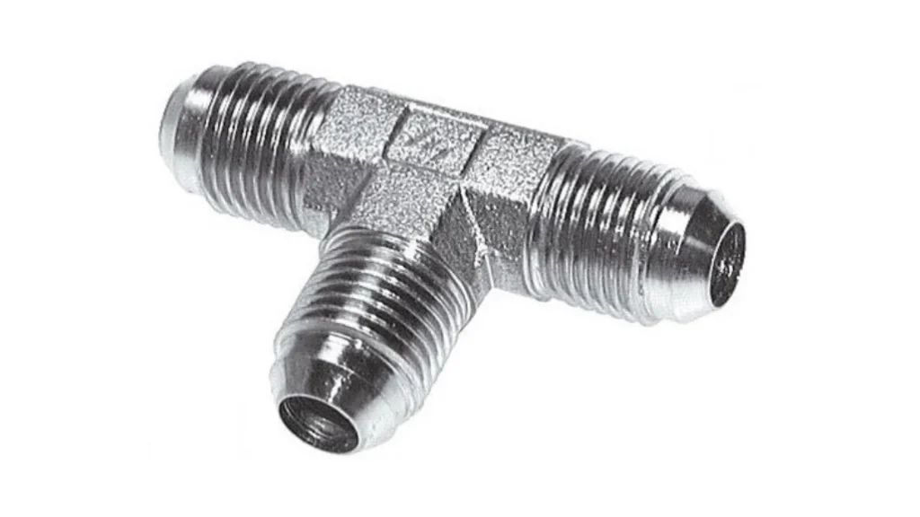
JIC fittings are typically used in hydraulic systems and consist of a male or female fitting with a 37-degree flare. The design allows for a secure, leak-free connection, commonly employed in high-pressure hydraulic lines.
Common Sizes of JIC fittings
The most common sizes for JIC fittings are #4, #6, #8, #10, #12, and #16. The number represents the size of the fitting in 1/16-inch increments. For example, a #6 fitting measures 6/16 inches (or 3/8 inches).
Common Specification Sizes of JIC fittings In Table:
| Size Label | Cone Width “a” (inches) | Thread Width “b” (inches) | Thread Specification “c” | Shoulder Width “d” (inches) | Shoulder Diameter “e” (inches) | Fitting Length “f” (inches) | Bore Diameter “h” (inches) | Tip Diameter “i” (inches) |
|---|---|---|---|---|---|---|---|---|
| 2 | 0.111 | 0.208 | 5/16”-24 unf | 0.067 | 0.250 | 0.448 | 0.062 | 0.083 |
| 3 | 0.11 | 0.239 | 3/8”-24 unf | 0.067 | 0.312 | 0.479 | 0.125 | 0.146 |
| 4 | 0.114 | 0.282 | 7/16”-20 unf | 0.080 | 0.364 | 0.550 | 0.172 | 0.193 |
| 5 | 0.114 | 0.282 | 1/2”-20 unf | 0.080 | 0.426 | 0.550 | 0.234 | 0.255 |
| 6 | 0.108 | 0.275 | 9/16”-18 unf | 0.090 | 0.481 | 0.556 | 0.281 | 0.318 |
| 8 | 0.155 | 0.310 | 3/4”-16 unf | 0.098 | 0.659 | 0.657 | 0.406 | 0.426 |
| 10 | 0.155 | 0.385 | 7/8”-14 unf | 0.111 | 0.772 | 0.758 | 0.531 | 0.539 |
| 12 | 0.185 | 0.424 | 1 – 1/16”-12 un | 0.130 | 0.943 | 0.943 | 0.609 | 0.664 |
| 14 | 0.186 | 0.450 | 1 – 3/16”-12 un | 0.129 | 1.068 | 0.890 | 0.719 | 0.788 |
| 16 | 0.186 | 0.471 | 1 – 5/16”-12 un | 0.129 | 1.193 | 0.911 | 0.844 | 0.913 |
Applications of JIC fittings
- Hydraulic Systems: In hydraulic machinery like excavators, bulldozers, and hydraulic presses, JIC fittings are used to connect hoses and pipes that carry high-pressure hydraulic fluid. Their ability to withstand high pressures and maintain a leak-free connection is essential for the proper functioning of these systems.
- Automotive Applications: They are found in automotive fuel lines, brake systems, and power steering systems. In fuel lines, for example, JIC fittings ensure that fuel is transported safely from the tank to the engine without any leaks, which is crucial for both performance and safety.
- Industrial Equipment: In factories, JIC fittings are used in a variety of equipment such as compressors, pneumatic tools, and cooling systems. They are reliable for connecting pipes that carry different types of fluids, including air, water, and industrial chemicals.
Characteristics of JIC fittings
- High-Pressure Resistance: Thanks to their well-designed flared and threaded connection, JIC fittings can withstand extremely high pressures. This makes them suitable for applications where pressure can reach several thousand pounds per square inch.
- Leak – Tight Sealing: The 37-degree flare design creates a tight seal when properly assembled. This ensures that there are no leaks, which is vital for systems handling fluids or gases.
- Versatility: With a wide range of sizes and types available, JIC fittings can be used in various applications, from small-scale DIY projects to large-scale industrial installations.
- Durability: Made from materials such as stainless steel, brass, and carbon steel, JIC fittings are durable and can withstand harsh environments, including exposure to moisture, chemicals, and high temperatures.
Preparations Before Measure JIC Fittings
How to Measure JIC Fittings: Tools Needed
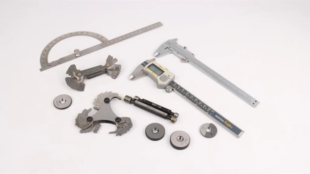
- Calipers: I always keep a set of digital calipers on hand. They are extremely accurate and can measure both inside and outside diameters. When measuring JIC fittings, I use them to measure the diameter of the threads, the flare, and the overall length of the fitting.
- Thread Gauges: To accurately measure the thread pitch and determine the thread type (e.g., UNF, UNC – Unified National Coarse), thread gauges are indispensable. They come in sets with different pitch sizes, and by matching the gauge to the threads on the JIC fitting, I can quickly identify the correct thread specification.
- Cone Gauges: For measuring the 37-degree flare angle of JIC fittings, cone gauges are essential. These gauges are precisely machined to the correct angle, allowing me to check if the flare on the fitting is within the required tolerance.
- Depth Gauge: When measuring the depth of recesses or the length of certain parts of the JIC fitting, a depth gauge is very useful. It helps me get accurate measurements for parts that are not easily accessible with regular calipers.
How to Measure JIC Fittings: Safety Precautions
Before starting any measurement, I always make sure to take the necessary safety precautions. If the JIC fitting is part of an active system, I ensure that the system is depressurized.
In the case of hydraulic systems, this means relieving all the pressure in the lines. I also wear safety glasses to protect my eyes from any potential debris that might dislodge during the measurement process.
When handling fittings that may be hot or have been in contact with chemicals, I use appropriate gloves.
How to Measure JIC Fittings for Different Dimensions
Measuring Thread Parameters of JIC Fittings
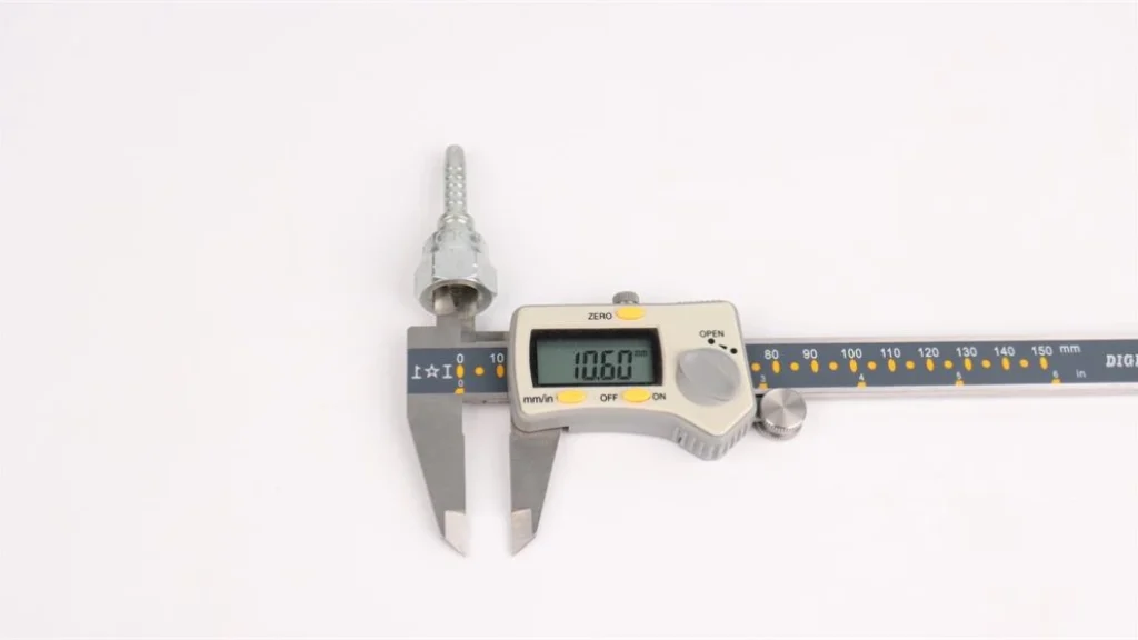
- Step 1: Measuring Thread Diameter
- First, I use my digital calipers to measure the outside diameter of the male thread. I make sure to measure at several points along the thread to account for any potential irregularities. For the female thread, I use the inside measurement jaws of the calipers to measure the diameter of the threaded hole.
- When measuring, I ensure that the calipers are perpendicular to the axis of the thread to get an accurate reading. Any tilt can lead to an incorrect measurement.
- Step 2: Determining Thread Pitch
- I select a thread gauge from my set and try to match it to the threads on the JIC fitting. I start by gently placing the gauge on the threads and checking if the teeth of the gauge fit perfectly into the threads.
- Once I find the correct gauge that fits snugly, I note down the pitch value. This value is crucial as it determines the type of thread (e.g., a pitch of 20 threads per inch for a #4 JIC fitting indicates a 7/16”-20 UNF thread).
- Step 3: Checking Thread Engagement
- To ensure proper connection, I also check the length of the thread engagement. I use a depth gauge to measure how far the male thread can be inserted into the female thread. This measurement helps me determine if the threads are worn or if there are any obstructions that could affect the connection.
Measuring the Cone Angle and Inspecting the Sealing Surface
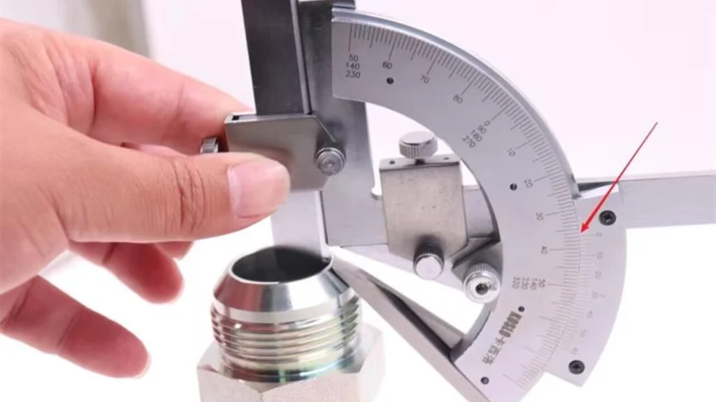
- Step 1: Measuring the Flare Angle
- I take the cone gauge that corresponds to the 37-degree angle of the JIC fitting. I carefully place the gauge over the flare of the male fitting.
- I check if the flare of the fitting matches the gauge perfectly. If there is a gap or if the fitting does not fit evenly against the gauge, it indicates that the flare angle may be incorrect. This could lead to a poor seal when the fitting is assembled.
- Step 2: Inspecting the Sealing Surface
- I use a magnifying glass to closely inspect the sealing surface of both the male and female fittings. I look for any signs of scratches, dents, or corrosion.
- Even a small imperfection on the sealing surface can cause a leak. If I find any defects, I may need to repair or replace the fitting. I also check for any foreign particles that may be stuck on the sealing surface and clean them thoroughly.
Measuring Bore Diameter and Length of JIC Fittings
- Step 1: Measuring the Bore Diameter
- For measuring the bore diameter of the JIC fitting, I use the inside-measurement jaws of my calipers. I insert the calipers into the bore and open them until they touch the inner walls of the fitting.
- I make sure to measure at different points along the bore to ensure that the bore is uniform. Any variation in the bore diameter can affect the flow of fluid through the fitting.
- Step 2: Measuring the Overall Length
- To measure the overall length of the JIC fitting, I use the calipers or a ruler, depending on the size of the fitting. I measure from one end of the fitting to the other, making sure to include any threaded portions or flanges.
- For fittings with complex shapes, I may need to break down the measurement into smaller parts and add them together to get the accurate overall length.
Selecting the Right JIC Fitting Size
Based on System Pressure Requirements of JIC Fittings
If the system operates at high pressures, I need to choose a larger-sized JIC fitting. Larger fittings can generally withstand higher pressures due to their thicker walls and larger connection areas.
For example, in a hydraulic system that operates at over 3000 psi, I would likely choose a #10 or larger JIC fitting.
Flow Rate Considerations of JIC Fittings
The flow rate of the fluid in the system is another important factor. If there is a high-volume flow of fluid, a larger-bore JIC fitting is required to ensure that there is no significant pressure drop.
For a system with a large-volume water flow, I would select a fitting with an appropriate bore diameter to maintain the desired flow rate.
Compatibility with Existing Components
When replacing or adding a JIC fitting to an existing system, I must ensure that the size is compatible with the other components. This means checking the thread size, flare size, and overall dimensions of the fittings that it will be connected to.
If I’m replacing a #6 JIC fitting in a fuel line, I need to make sure the new fitting has the same thread and flare specifications to ensure a proper connection.
Key Considerations and Error Analysis
Key Considerations for Measure JIC Fittings
Consistent Measurement Technique
I always make sure to use the same measurement technique every time. For example, when measuring thread diameter, I always measure at the same relative position on the thread. Inconsistent techniques can lead to inaccurate and unreliable measurements.
Proper Tool Calibration
Regularly calibrating my measurement tools is essential. I send my calipers and gauges for calibration at least once a year. Using uncalibrated tools can introduce significant errors in the measurement.
Environmental Factors
I take into account environmental factors such as temperature. Some materials, like metal, can expand or contract with temperature changes. If I’m measuring a JIC fitting in a hot environment, I may need to wait for it to cool down to room temperature for accurate measurements.
Error Analysis Measure JIC Fittings
Human Error
One of the most common sources of error is human error. This can include incorrect reading of the measurement tool, improper alignment of the tool with the fitting, or inconsistent measurement techniques. To minimize this, I always double-check my measurements and take multiple readings.
Tool Error
Even with calibrated tools, there can be some inherent errors. For example, calipers may have a small margin of error in their readings. I account for this by using tools with the highest accuracy possible and by understanding the error tolerance of each tool.
Fitting Condition
The condition of the JIC fitting itself can affect the measurement. If the fitting is worn, damaged, or has been repaired, it may not have the exact dimensions of a new fitting. I always inspect the fitting thoroughly before measuring and take into account any visible defects.
Conclusion
In conclusion, accurately measuring JIC fittings is essential for ensuring the proper functioning and safety of fluid-handling systems.
By following the steps outlined in this article, using the right tools, and being aware of potential errors, you can take precise measurements of JIC fittings.
Whether it’s measuring the thread parameters, the flare angle, or the bore diameter, each measurement plays a crucial role in the selection and installation of the fitting. If you are interested in our products, you can visit our homepage or ask us for a product catalog.
FAQs About How to Measure JIC Fittings
How do I know what size JIC fitting I have?
You can determine the size of your JIC fitting by measuring the outside diameter of the fitting’s threads and referring to a size chart for JIC fittings. If the fitting is already installed, check the hose size to find the corresponding fitting size.
What size is a #8 JIC fitting?
A #8 JIC fitting has a 3/8-inch outer diameter. This is a common size used in hydraulic systems for medium-pressure applications.
How do you tell what size a hydraulic fitting is?
To determine the size of a hydraulic fitting, measure the outer diameter of the threads and the length of the fitting. You can then cross-reference these measurements with a fitting size chart for accurate identification.
How to identify fitting size?
To identify the size of a fitting, measure the thread diameter (outer diameter) and the thread pitch. You can also use a thread gauge to verify the pitch and ensure compatibility with the hose or tube.
How do I measure a JIC fitting size?
To measure a JIC fitting, you need to check the thread diameter, flare angle, sealing surface, and overall fitting length. Use tools like calipers, protractors, and thread gauges to get accurate measurements.
Where to buy JIC fittings?
For high-quality JIC fittings, look no further than Dingfeng. We offer a full range of JIC fittings and custom solutions tailored to your needs. Contact us directly for product inquiries, or visit our homepage to explore our full catalog.